This Macintosh Plus Has No Display. Can It Be Fixed?

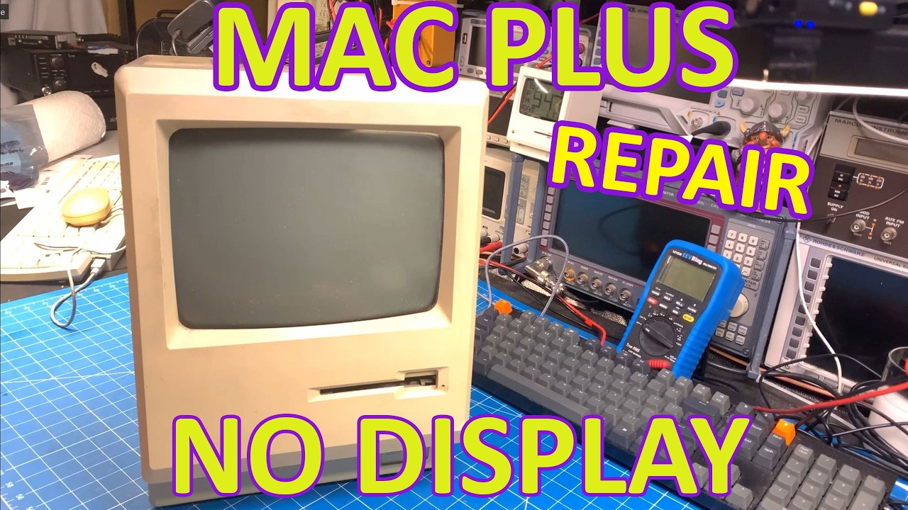
The Macintosh Plus is a beloved piece of computing history, known for its iconic design and significant contributions to personal computing. However, like many vintage electronics, it can suffer from various issues over time, including display problems. In a recent video, a dedicated technician undertakes the challenge of repairing a Macintosh Plus that has lost its display functionality. This repair process involves two critical tasks: re-capping the analog board and rebuilding the analog to logic board cable.

Understanding the Problem

The video begins with a thorough examination of the Macintosh Plus to identify the root cause of the display failure. The technician explains that older electronic components, especially capacitors on the analog board, can degrade over time, leading to malfunction. The analog board is responsible for converting signals so that the display can render images, making it a crucial component in the functioning of the Macintosh Plus. By addressing the analog board, the technician aims to restore the display to its former glory.

Re-Capping the Analog Board

Re-capping, the process of replacing old capacitors with new ones, is a standard procedure in repairing vintage electronics. The video showcases the step-by-step approach taken by the technician, highlighting the importance of using high-quality replacement parts. The video also features a detailed parts list, accessible through a provided link, ensuring that viewers can easily find the necessary components for their own repair projects. This transparency not only empowers viewers but also fosters a community of enthusiasts who appreciate the intricacies involved in vintage tech repair.

Rebuilding the Analog to Logic Board Cable

In addition to re-capping the analog board, the technician also focuses on rebuilding the cable that connects the analog board to the logic board. This cable is vital for transmitting signals between the two boards. Throughout the video, the technician emphasizes the careful handling of components and the precision required to ensure a successful repair. By showcasing this process, the video educates viewers on the significance of every part in the system and the meticulous work needed to restore functionality.

Conclusion: A Journey of Restoration

The repair of the Macintosh Plus serves as a reminder of the durability and charm of vintage technology. By diving into the intricacies of the repair process, the technician not only aims to fix a classic machine but also inspires others to engage with their own vintage electronics. The detailed approach and the sharing of resources encourage a sense of community among tech enthusiasts, proving that with the right knowledge and tools, even the most challenging repairs can be tackled. Whether you’re a seasoned repair expert or a curious beginner, this journey of restoration highlights the rewarding experience of bringing old technology back to life.

In this video we repair a Macintosh plus. Re-capping the analog board and rebuilding the analog to logic board cable.

Analog board parts list: https://docs.google.com/spreadsheets/d/132RwzC8HM5ask-BdY_31txErOCwJDSkz099GY2XLpE0/edit?usp=sharing

Watch on YouTube: This Macintosh Plus Has No Display. Can It Be Fixed?

Subscribe: Click here

Motorola CDM Series Head Swap and Channel Mod

In the world of radio communications, the Motorola CDM series stands out for its versatility and user-friendly design. In a recent video tutorial, enthusiasts learned how to swap heads between different CDM models, such as the 1250 and 750, making it easier to adapt radios for varying needs. The tutorial emphasizes that these swaps can be performed across different frequency bands, whether VHF or UHF, which adds an exciting layer of customization to these devices.

Getting Started with Head Swapping

The video kicks off with an introduction to the different types of control heads available in the CDM series. The speaker showcases a VHF radio equipped with a single-line display, a common choice among users. After powering up the radio and confirming its functionality, the process of swapping the head begins. The speaker demonstrates how to turn off the radio, unplug the power, and replace the head with a more advanced Passport model. However, upon restarting, a “wrong control head type” error appears, which is a common issue when mismatching heads.

Fixing the Control Head Error

To resolve the error, the speaker introduces the necessary programming cable, which can easily be found on platforms like Amazon. This cable connects the radio to a computer, enabling the use of Chirp software for programming. However, it is crucial to use an older version of Chirp to avoid compatibility issues with the specific plugin required for this task. The tutorial walks viewers through the steps of loading the plugin and configuring the radio settings, ensuring that the new head is recognized correctly.

Expanding Channel Limits

In addition to simply swapping heads, the tutorial dives deeper into the customization options available through the programming software. The speaker reveals how users can increase the conventional channel limit to a maximum of 255 channels and set trunking channel limits to one. This flexibility allows radio operators to maximize their devices’ capabilities, catering to a wide range of communication needs. The tutorial also advises caution when experimenting with advanced settings, recommending that users stick to the essential adjustments to avoid potential issues.

Final Thoughts

The video concludes with a reminder that while Chirp is a useful tool for monitoring and some programming tasks, users must rely on Motorola’s CPS for comprehensive radio programming. This distinction is vital for ensuring the radio operates correctly after modifications. The speaker encourages viewers to engage with the content, share their thoughts, and stay tuned for more informative tutorials. With this knowledge, CDM series users can confidently adapt their radios for enhanced performance and functionality.

How to swap heads between the different models of the CDM Series. Also how to expand to 255 conventional channels!

Credit goes to W9CR. Check out their website for tons of cool info on modding these radios. https://wiki.w9cr.net/index.php/Waris

Watch on YouTube: Motorola CDM Series Head Swap and Channel Mod

Subscribe: Click here

Icom IC-F110 & IC-F121 LCD Repair

Welcome back to the bench! In this engaging video, our host dives into the world of repairing the Icom IC-F110, a member of the F100 series radios. The main issue at hand? An LCD that’s not functioning as it should. With a collection of these radios on hand, the host embarks on a journey to diagnose and fix this particular device, promising a straightforward repair process.

Diagnosis and Initial Findings

Upon powering up the radio, it becomes evident that while the channel changing function operates fine, the LCD display is not fully responsive. This leads our technician to suspect dirty contacts or potentially a faulty ribbon cable, rather than a more complex voltage or regulator issue. A quick check of the connections reveals that there might have been liquid spillage, possibly coffee or soda, contributing to the LCD malfunction. With a plan in place, the host begins the disassembly process to get to the root of the problem.

Disassembly and Cleaning Process

The disassembly involves careful handling of various components, including unplugging the ribbon cable and speaker cable. As the host removes the main board, a clear indication of liquid damage becomes visible—the LCD is sticking to the base, hinting at previous spills. Cleaning the device is crucial, which leads to a thorough wash of the housing and buttons in warm, soapy water, while taking care not to damage the glued speaker.

Restoring the LCD Functionality

Once the exterior is clean, the technician turns attention to the internal components. The LCD screen, zebra strip, and other parts are meticulously cleaned with isopropyl alcohol and Q-tips to remove any residue that could affect performance. The host notes that the zebra strip, which is essential for connecting the LCD to the main circuit board, was particularly dirty, prompting the need for a detailed clean to restore functionality.

Final Assembly and Testing

After a comprehensive clean-up, the technician reassembles the radio, ensuring each component is placed back as it was originally positioned. The moment of truth arrives when the radio is powered on again, and to the host’s relief, the LCD displays properly. With the repair complete, the technician reflects on the satisfaction of restoring this device to working condition and prepares to move on to the next radio in need of repair.

This video not only sheds light on the practical aspects of electronic repair but also highlights the importance of proper cleaning and maintenance for devices prone to liquid damage. With a few straightforward steps, even problematic radios can be revived, ensuring they continue to serve their purpose effectively!

Repairing a faulty LCD screen on a Icom IC-F110 / IC-F121 radio.

Watch on YouTube: Icom IC-F110 & IC-F121 LCD Repair

Subscribe: Click here

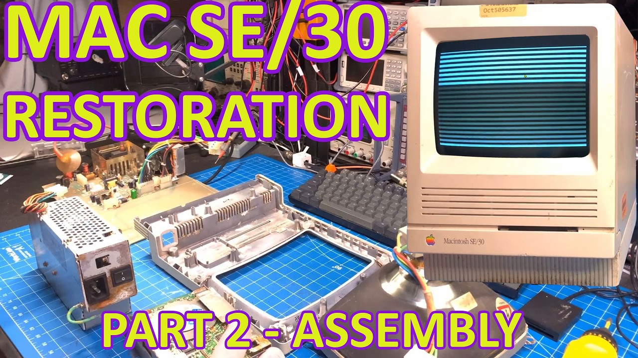
Macintosh SE/30 – Restoration Part 2 – Re-assembly

In the latest installment of the Macintosh SE/30 restoration series, the host dives back into the intricacies of reassembling a classic piece of computing history. After tackling severe corrosion issues in the previous video, the focus shifts to reassembling the cleaned and restored components. The host shares insights into the process, showcasing a beautifully restored frame that has been treated with Rustoleum cold galvanized paint, effectively eliminating rust and corrosion. While some stains remain on the faceplate—likely from leaked alkaline—the restoration is progressing well, setting the stage for a successful reassembly.

Restoring the Core Components

One of the significant challenges faced by the host was dealing with the analog board, which had suffered extensive corrosion. Instead of using the original damaged board, the restoration involves a replacement from a donor Macintosh SE. This replacement has been reflowed and soldered to ensure stable connections. The speaker has been carefully reattached with a bit of glue, and new screws have been utilized to replace the corroded originals, ensuring that the assembly remains robust and reliable.

Innovative Upgrades and Modifications

The host also introduces several upgrades to enhance the Macintosh’s performance and usability. While the original hard drive remains installed for aesthetic and monetary value, a Blue SCSI device is integrated to provide modern storage capabilities. A new 3D-printed mount allows for a more seamless installation, ensuring that the Blue SCSI fits flush with the case. This modification exemplifies the blend of vintage technology with modern solutions, creating a more functional and appealing system.

Enhancing the Motherboard

Moving on to the motherboard, the host showcases various enhancements, including the installation of a coin cell battery insert and upgraded RAM. The use of purple RAM and ROM not only adds a visual flair but also allows for customization and improved performance. The host emphasizes the importance of using 3D-printed clips to secure the newer RAM, which ensures stability and prevents potential issues during operation. These thoughtful upgrades help revitalize the Macintosh SE/30, allowing it to meet contemporary standards while retaining its classic charm.

Final Testing and Observations

As the assembly comes together, the host takes the time to test the system before sealing it up entirely. The excitement is palpable as the Macintosh boots up successfully, revealing a vibrant screen free from burn-in or blurriness. The careful adjustments and meticulous cleaning have paid off, resulting in a machine that looks almost as good as new. While there are still minor cosmetic imperfections, the overall restoration is impressive, promising a rewarding experience for anyone who gets to use this classic computer.

With the project nearing completion, the host expresses enthusiasm for the potential of the restored Macintosh SE/30. The journey of bringing this vintage machine back to life showcases not only the technical skills involved but also the joy of preserving computing history. As the video wraps up, viewers are left eager for the next installment, where the restoration of additional components from the donor SE will be explored in further detail.

Back again with this SE/30. Let's put it all back together.

Watch on YouTube: Macintosh SE/30 – Restoration Part 2 – Re-assembly

Subscribe: Click here

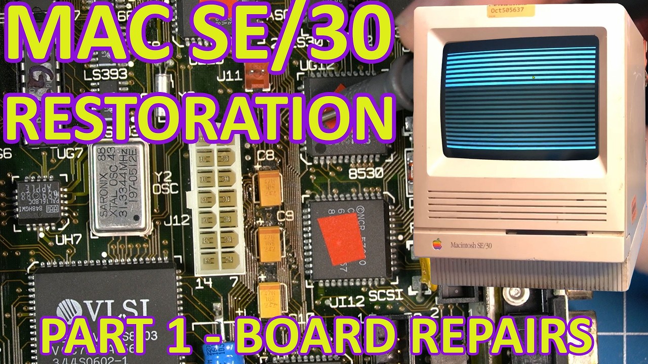
Macintosh SE/30 – Restoration Part 1 – Logic board repair #marchintosh

In a fascinating journey of retro tech restoration, the latest episode on restoring a Macintosh SE/30 takes viewers through a meticulous process of diagnosing and repairing a classic computer. From the outset, the host reveals the unit’s condition, including a dirty case with evident scuff marks and a malfunctioning floppy drive showing signs of corrosion, which raises concerns about potential battery leakage. Fortunately, the speaker quickly assesses that the battery itself has not caused severe damage, with the primary culprit likely being leaking capacitors, a common issue with this model.

Initial Assessment and Diagnosis

Upon disassembling the Macintosh SE/30, the host uncovers significant corrosion on the logic board, particularly around the floppy drive and various chips. Despite the grim state of the board, it presents an advantage due to its older revision, featuring a socketed CPU. This allows for easier testing and potential swapping of components. After a thorough cleaning of the board, the discussion shifts to troubleshooting, where the speaker employs a detailed schematic to identify possible faults in the RAM and ROM connections. This meticulous approach sets the stage for a deeper exploration of data lines and their connections on the board.

Testing and Troubleshooting

As the restoration progresses, the host utilizes a systematic method to check the continuity of data lines, employing a matrix from the schematic as a reference. This methodical testing reveals a significant issue with data line 28, which is found to be shorted to the 5V rail. The speaker hypothesizes that either a faulty chip or a corroded trace could be responsible for this short circuit. The process involves isolating various chips by cutting traces on the board to pinpoint the exact source of the problem. The host’s careful explanation of this troubleshooting process demystifies the complexities involved in diagnosing vintage computer logic boards.

Discovering the Problem

In a surprising twist, the culprit for the short circuit is identified as a tiny solder ball that had formed during previous repairs. The host reveals how this minor oversight created significant issues, illustrating the challenges of working with older technology. After addressing the short, the speaker proceeds to make a bodge wire connection to restore functionality to data line 28. This hands-on approach showcases the intricate relationship between hardware repair and troubleshooting, revealing the patience and skill required to breathe new life into vintage machines.

Successful Boot and Next Steps

With the short resolved, the moment of truth arrives as the Macintosh SE/30 is powered on. The familiar chime signals progress, indicating that critical components are functioning correctly. However, the host encounters another hurdle with the RAM, which turns out to be faulty. This common issue with older computers leads to further testing and replacement of RAM modules, ultimately resulting in a successful boot into the operating system. The excitement in the host’s voice is palpable as they share the satisfaction of overcoming these challenges.

As the first part of this restoration journey concludes, viewers are left with a sense of anticipation for the upcoming episodes. The speaker promises to tackle the restoration of the chassis and other enhancements in the next installment, encouraging the audience to join in this thrilling march of Macintosh restoration. With a blend of technical expertise and engaging storytelling, the video captures the essence of vintage computing and the joy of bringing old systems back to life.

In this video we will start restoring a Macintosh SE/30 with some corrosion on the board and chassis. This Mac is showing Horizontal lines which is a very common problem, often called Simasimac.

Watch on YouTube: Macintosh SE/30 – Restoration Part 1 – Logic board repair #marchintosh

Subscribe: Click here

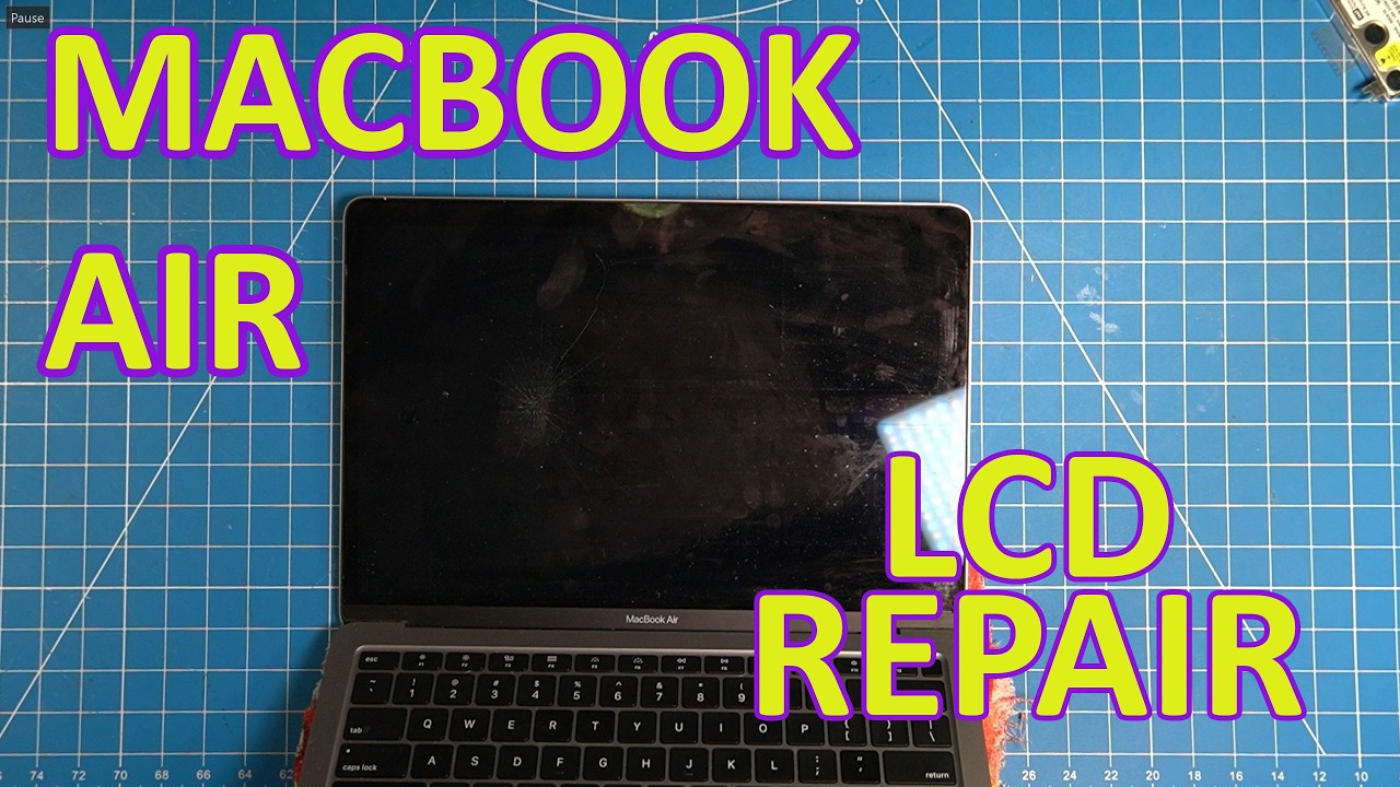
MacBook Air LCD Screen replacement

If you’ve ever faced the frustrating experience of a damaged MacBook Air screen, you know how daunting the repair process can seem. In a recent video, a tech enthusiast walks viewers through the intricate steps of replacing the LCD screen on a 2020 MacBook Air model 1279, sharing tips and insights that make the process easier and more accessible for DIYers. Armed with just a few tools and a replacement screen sourced from AliExpress, he dives headfirst into the repair, demonstrating that with patience and the right approach, tackling such tasks can be rewarding.

Assessing the Damage

The adventure begins with a thorough inspection of the damaged screen, revealing a spiderweb of cracks that signal a need for replacement. The speaker emphasizes the importance of sourcing the correct parts, noting that while many kits come with complete assemblies, his journey will focus on replacing just the LCD glass panel itself. This decision sets the stage for a more detailed and challenging repair process, as he aims to delve deeper than typical replacements.

Gathering Tools and Disconnecting the Battery

Before starting, he gathers an array of tools, including a Torx screwdriver set, and emphasizes the necessity of disconnecting the battery to prevent any electrical mishaps. He meticulously removes screws and connectors, ensuring each piece is organized in a magnetic tray to avoid losing any small components. This methodical approach is crucial in maintaining order throughout the disassembly process, which can often become chaotic without proper organization.

Removing the Old Screen

As he progresses, the speaker encounters the delicate task of separating the LCD from the frame. Using a thin plastic tool, he carefully pries up the screen, sharing the importance of caution to avoid damaging the fragile backlight. Despite his best efforts, he faces challenges, including the unavoidable breaking of the plastic trim piece—an unfortunate but common occurrence in such repairs. The speaker advises viewers to be prepared for these potential setbacks and to order replacement parts in advance.

Reassembly and Final Touches

Once the old screen is out, he cleans the area and prepares the new LCD for installation. He applies double-sided adhesive and carefully repositions the rubber seal around the perimeter. The reassembly phase requires precision; alignment is key to ensuring a seamless fit. The speaker also highlights the importance of checking for dust and debris before sealing everything up, as any foreign particles could mar the new screen’s clarity.

Lessons Learned and Final Thoughts

In conclusion, this repair journey not only offers practical guidance for those looking to replace their MacBook Air screens but also shares valuable lessons learned along the way. The speaker reflects on the time-consuming nature of the process and hints that for future repairs, he might opt for a complete screen assembly rather than going through the extensive disassembly. His experience serves as a reminder that while DIY repairs can save money, they also require a careful balance of skill, patience, and the right tools. For anyone considering a similar repair, this video is a treasure trove of insight and encouragement!

Lets swap out an LCD screen on a Macbook Air. This is not fun!

Watch on YouTube: MacBook Air LCD Screen replacement

Subscribe: Click here

Bringing a Dead Macintosh SE/30 Back to Life

Welcome back to the bench, where retro computing meets hands-on repairs! In this latest adventure, we dive into the restoration of a Macintosh SE/30, often hailed as the holy grail of compact Macs. This particular unit exhibits a bad display and some noticeable burn-in, but it promises to be an exciting project. The speaker highlights a unique addition to this Mac: a rather unattractive space saver power selector switch with a built-in fan designed to enhance airflow. Despite its looks, this component might just stay as a quirky feature of the restoration.

Upon opening the SE/30, the technician finds an impressively clean case with no cracks or major signs of wear, although it does have its fair share of dust. Excitingly, the board appears intact with no battery leakage so far, which is always a concern in vintage electronics. However, the presence of capacitor leakage is quickly noted, prompting the speaker to prepare for a thorough clean-up. After removing the motherboard, he discovers that the dust has actually played a protective role, absorbing most of the leaking capacitor fluid before it could cause significant damage.

As the restoration progresses, the technician encounters a small setback when desoldering a capacitor leads to a broken trace on the motherboard. This ‘bodge’ repair becomes a necessary part of the process, highlighting the often unpredictable nature of vintage electronics repairs. With the capacitors replaced and the board cleaned up, the speaker tests the system’s components, discovering that it has only 5 megabytes of RAM, which explains its sluggish performance.

In an effort to modernize the SE/30, the technician installs a Rominator 2 and a Vominator 2 from Big Mess of Wires, upgrading the RAM to a much more efficient 64 megabytes. Excitement builds as the machine powers up successfully, displaying a pirate face and recognizing the new RAM. With a Blue SCSI drive connected, the speaker is thrilled to find that the system is configured for Wi-Fi and running System 7.12, making it a functional, modernized unit.

As the restoration nears completion, the speaker reflects on the cosmetic condition of the SE/30, noting that it is one of the best he has encountered. Despite some minor scuff marks, the case remains free of cracks, promising a bright future for this classic computer. Looking ahead, the speaker hints at upcoming projects involving more SE/30s, blending a love for retro computing with a commitment to sharing the journey. As he prepares to tackle a variety of repairs beyond just Macs, viewers can expect a mix of vintage projects that will keep the spirit of restoration alive.

In this video we re-cap a Macintosh SE30 logic board and throw in some modern goodies to speed things up.

#marchintosh

Watch on YouTube: Bringing a Dead Macintosh SE/30 Back to Life

Subscribe: Click here

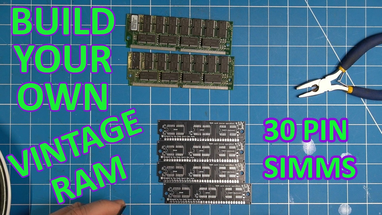
How to make your own 30 pin Ram Simms

Welcome back to the bench! In today’s exciting DIY project, we dive into the world of retro computing by building our own RAM SIMs using a kit from the Satanic Mac Club. This project isn’t just for Mac enthusiasts; you can use these RAM SIMs in any old system that requires 30 pin RAM. As 30 pin RAM becomes increasingly scarce, this guide will show you how to repurpose 72 pin RAM chips into functional 30 pin RAM, making it an appealing option for retro computing aficionados.

The Benefits of Creating Your Own RAM SIMs

One of the main reasons to undertake this project is the availability of components. Many vintage systems require 30 pin RAM, which is becoming harder to find, especially in larger capacities like 4MB. By taking 16MB chips from 72 pin SIMs—which are much easier to source—you can effectively create multiple 4MB SIMs. This is not only a cost-effective solution but also a way to breathe new life into older systems that require upgraded memory.

Getting Started: Preparing Your Components

The first step in this project is preparing the components. The speaker demonstrates breaking off extra pieces from the 72 pin RAM chips and carefully tinning the pads on the PCBs where the chips will be installed. Using hot air for both the removal and installation of these chips ensures a clean process and minimizes damage. The importance of flux is emphasized, as it helps solder adhere smoothly to the pads. After applying flux, the chips are positioned carefully over the pads for soldering.

Assembly Process: Soldering the RAM Chips

During the assembly, the speaker highlights the technique of heating the entire chip uniformly to allow it to settle into place correctly. This process requires patience as the chips can wiggle before properly aligning themselves with the pads. Once the chips are in place, additional components like capacitors, resistors, and an optional LED can be soldered onto the PCB, enhancing both functionality and aesthetics. The speaker shares handy tips on how to avoid common pitfalls during soldering, such as ensuring the components sit straight before securing them.

Testing Your New RAM SIMs

After completing the soldering process, the newly assembled RAM SIMs undergo a thorough cleaning to remove excess flux and ensure a professional finish. Following this, the SIMs are tested in a Macintosh Color Classic board, allowing for practical verification of their functionality. The excitement builds as the system recognizes the RAM, displaying a total of 10MB—its maximum capacity—demonstrating that the DIY project was a success!

In conclusion, this engaging video not only teaches viewers how to create their own 30 pin RAM SIMs but also highlights the importance of resourcefulness in retro computing. By repurposing more readily available components, hobbyists can continue to enjoy and restore vintage systems with upgraded performance. Be sure to like and subscribe for more exciting DIY projects and retro computing adventures!

Build your own 30 pin RAM using easier to find 72-pin RAM as a doner.

Buy the PCB's from the link below. You can also get a list of compatible RAM chips from the same site. https://en.infinityproducts.co.jp/product-page/smc-4mb-memory-card-diy-kit

#marchintosh

Watch on YouTube: How to make your own 30 pin Ram Simms

Subscribe: Click here

Amazon Fire TV Remote Repair

In today’s tech-driven world, even the most reliable gadgets can occasionally fail us, and the Amazon Fire TV remote is no exception. In this engaging repair tutorial, the speaker dives into the troubleshooting and repairing process of a seemingly dead Fire TV remote, sharing insights and tips along the way. With new batteries installed and the usual pairing tricks attempted, the remote remained unresponsive, prompting the need for a deeper investigation into its inner workings.

Opening the Remote

The first step in the repair process involved opening the remote to assess the problem. The speaker quickly discovered that modern remotes are typically made of plastic, which can be tricky to navigate. While attempting to pry it open, they realized there were screws that needed to be removed. Although this led to a bit of damage, the speaker was able to successfully access the internal components. This experience highlights a critical aspect of DIY repairs: always be prepared for unexpected challenges and take care to avoid unnecessary damage.

Diagnosing the Issue

Upon opening the remote, it became clear that the issue might stem from a soldering problem on the circuit board. The speaker noted that there was no voltage detected on some parts of the board, which indicated a potential connection issue. However, they found that by applying pressure to a specific solder ball, the infrared light began to function, suggesting that the connections were indeed faulty. This moment of discovery emphasized the importance of careful diagnostics in any repair process.

Repairing the Solder Connections

With the diagnosis in hand, the speaker proceeded to reflow the solder connections using lead-based solder. This technique involved melting the existing solder to create a better electrical connection, particularly where the connections seemed “wonky.” They also highlighted that while some connections were soldered from the front, others lacked adequate solder on the back, which could contribute to the functionality issues. This insight serves as a reminder of the importance of thoroughness in electronic repairs.

Testing the Repair

After completing the soldering repairs, the moment of truth arrived. The speaker pressed the power button, and to their delight, the infrared light activated, indicating that the remote was indeed functioning again. The volume controls also worked, confirming that the immediate problem had been resolved. However, they noted that the remaining functions, such as Bluetooth connectivity, would require further testing, especially since those features are crucial for the full functionality of the Fire TV.

This repair journey not only demonstrates the essential skills of troubleshooting and soldering but also offers viewers a firsthand look at the inner workings of a commonly used device. With a bit of patience and careful observation, many tech issues can be addressed without the need for professional help. For anyone facing similar problems with their Fire TV remote, this video serves as an encouraging guide to tackle the issue head-on!

It seems that these remotes are prone to failing, maybe you have this same problem? It turned out to be a simple fix with bad solder joints!

This should work for any of the cheap TV Remotes from amazon, roku, TCL.

Watch on YouTube: Amazon Fire TV Remote Repair

Subscribe: Click here

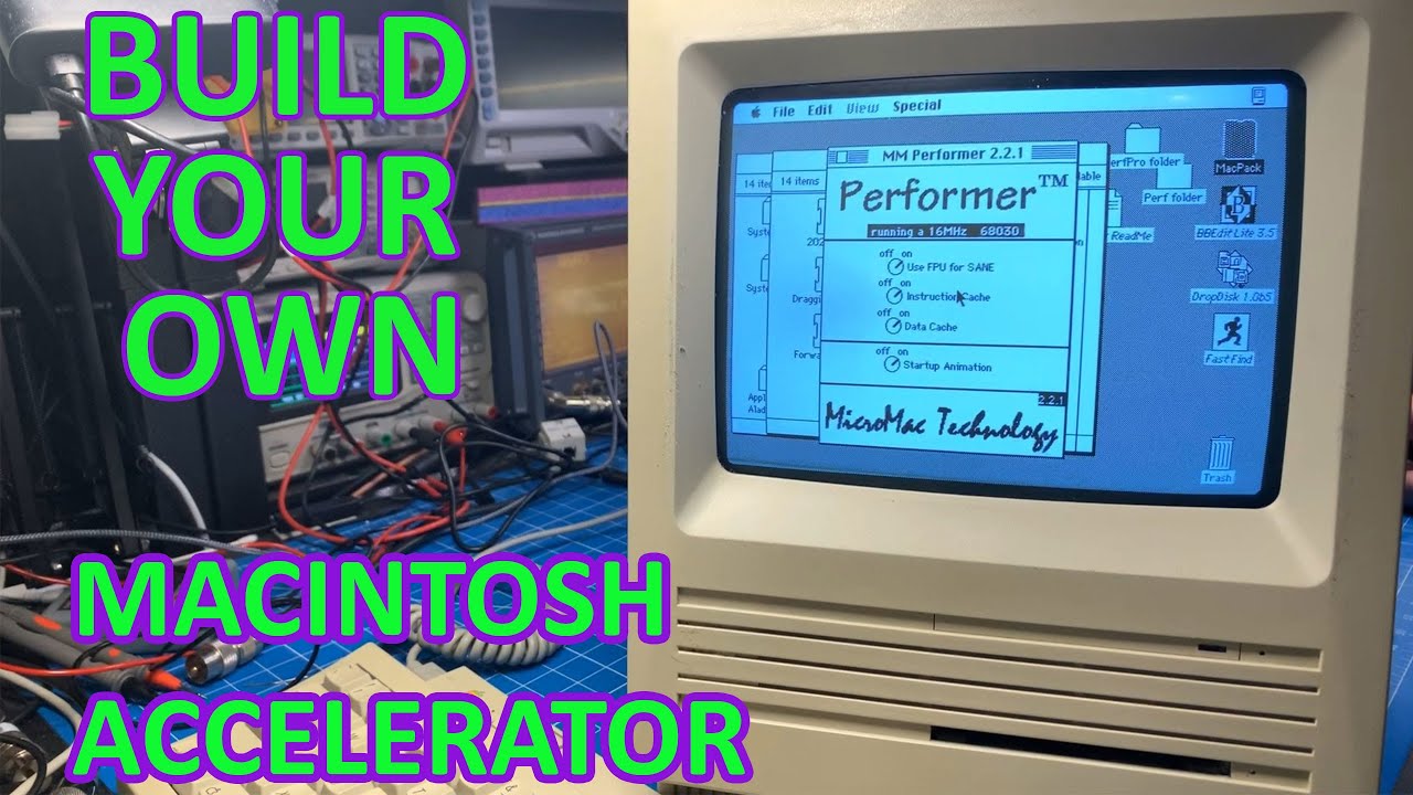
Build your own Accelerator for Macintosh SE, Plus or Classic

In a recent YouTube video, a tech enthusiast takes us through the process of building an accelerator board for classic Macintosh models, specifically the SE, Plus, and Classic. This project focuses on the Performer accelerator, which has been open-sourced by a well-known figure in the Macintosh community, Bull. With a rich history of creating various projects like the SE Reloaded and SE30 Reloaded boards, Bull has made it possible for hobbyists to access his designs on GitHub. While Mac Effects offers pre-built versions of this accelerator for $188 to $229 USD, the creator of the video decides to embark on a DIY journey, sourcing parts from platforms like AliExpress, eBay, and Digi-Key, ultimately aiming to build five units at a fraction of the cost.

The accelerator board is versatile, designed to fit into the PDS slot of an SE or to sit atop the existing CPU in any of the supported models. This flexibility allows users to enhance their vintage machines significantly, and the creator plans to test the accelerator in various Macintosh models, including the 512K. The project promises to be straightforward, although it requires a programmer for the GAL chips, which are critical for the board’s functionality. The speaker highlights a design quirk in the board that complicates troubleshooting: the GAL chips are not socketed, necessitating direct soldering—an unfamiliar territory for the creator.

One of the more innovative aspects of this project is the use of solder paste for attaching components. Despite initial challenges with the application and airflow, the creator manages to successfully solder passive components using this method. The learning curve becomes evident as they navigate through soldering techniques and component sizes, adapting as they go along. The speaker also mentions using through-hole tantalum capacitors instead of surface mount ones due to availability, emphasizing the project’s resourcefulness amid rising component prices.

As the build progresses, the speaker transitions to programming the GAL chips, an essential step for ensuring the board operates as intended. After programming each chip, they prepare for the final assembly, including installing a crystal filter to match the CPU and FPU speeds. They cleverly opt to use standard headers for the PDS slot instead of purchasing an expensive connector, further showcasing their DIY spirit and commitment to cost-saving measures.

Once assembled, the creator tests the accelerator in a Macintosh SE, navigating troubleshooting challenges to finally achieve success. They note that the accelerator runs the CPU at a locked speed of 16 MHz, even though the FPU can operate at a higher frequency. The performance boost is significant, bringing the Macintosh SE closer to the capabilities of the SE30. The video not only highlights the excitement of retro computing but also serves as a testament to the community’s dedication to preserving and enhancing vintage technology.

In conclusion, this project embodies the spirit of DIY innovation within the retro computing community. With the combination of open-source designs, resourceful sourcing, and a hands-on approach, the creator effectively demonstrates how to breathe new life into classic Macintosh computers. Viewers are left inspired and informed, eager to explore their own retro computing projects in the future.

Today I'm going to build some Accelerator boards that were open sourced by Bolle. It will work in the Macintosh Plus, SE, or Classic.

This is a clone of the Micromac Performer. You can build them yourself with the files at Bolle's Github: https://github.com/TheRealBolle/Performer-SE-PL-CL

Or you can buy them from Mac Effects pre made: https://maceffects.com/products/maceffects-performer-pds-68030-accelerator-for-apple-macintosh-se

Watch on YouTube: Build your own Accelerator for Macintosh SE, Plus or Classic

Subscribe: Click here