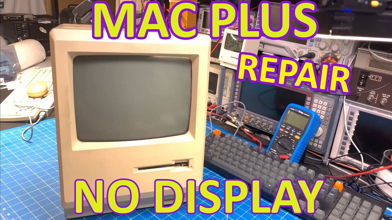
This Macintosh Plus Has No Display. Can It Be Fixed?

Full Video Description

In this video we repair a Macintosh plus. Re-capping the analog board and rebuilding the analog to logic board cable.

Analog board parts list: https://docs.google.com/spreadsheets/d/132RwzC8HM5ask-BdY_31txErOCwJDSkz099GY2XLpE0/edit?usp=sharing

Watch on YouTube: This Macintosh Plus Has No Display. Can It Be Fixed?

Subscribe: Click here

Motorola CDM Series Head Swap and Channel Mod

In the world of radio communications, the Motorola CDM series stands out for its versatility and user-friendly design. In a recent video tutorial, enthusiasts learned how to swap heads between different CDM models, such as the 1250 and 750, making it easier to adapt radios for varying needs. The tutorial emphasizes that these swaps can be performed across different frequency bands, whether VHF or UHF, which adds an exciting layer of customization to these devices.

Getting Started with Head Swapping

The video kicks off with an introduction to the different types of control heads available in the CDM series. The speaker showcases a VHF radio equipped with a single-line display, a common choice among users. After powering up the radio and confirming its functionality, the process of swapping the head begins. The speaker demonstrates how to turn off the radio, unplug the power, and replace the head with a more advanced Passport model. However, upon restarting, a “wrong control head type” error appears, which is a common issue when mismatching heads.

Fixing the Control Head Error

To resolve the error, the speaker introduces the necessary programming cable, which can easily be found on platforms like Amazon. This cable connects the radio to a computer, enabling the use of Chirp software for programming. However, it is crucial to use an older version of Chirp to avoid compatibility issues with the specific plugin required for this task. The tutorial walks viewers through the steps of loading the plugin and configuring the radio settings, ensuring that the new head is recognized correctly.

Expanding Channel Limits

In addition to simply swapping heads, the tutorial dives deeper into the customization options available through the programming software. The speaker reveals how users can increase the conventional channel limit to a maximum of 255 channels and set trunking channel limits to one. This flexibility allows radio operators to maximize their devices’ capabilities, catering to a wide range of communication needs. The tutorial also advises caution when experimenting with advanced settings, recommending that users stick to the essential adjustments to avoid potential issues.

Final Thoughts

The video concludes with a reminder that while Chirp is a useful tool for monitoring and some programming tasks, users must rely on Motorola’s CPS for comprehensive radio programming. This distinction is vital for ensuring the radio operates correctly after modifications. The speaker encourages viewers to engage with the content, share their thoughts, and stay tuned for more informative tutorials. With this knowledge, CDM series users can confidently adapt their radios for enhanced performance and functionality.

How to swap heads between the different models of the CDM Series. Also how to expand to 255 conventional channels!

Credit goes to W9CR. Check out their website for tons of cool info on modding these radios. https://wiki.w9cr.net/index.php/Waris

Watch on YouTube: Motorola CDM Series Head Swap and Channel Mod

Subscribe: Click here

Icom IC-F110 & IC-F121 LCD Repair

Welcome back to the bench! In this engaging video, our host dives into the world of repairing the Icom IC-F110, a member of the F100 series radios. The main issue at hand? An LCD that’s not functioning as it should. With a collection of these radios on hand, the host embarks on a journey to diagnose and fix this particular device, promising a straightforward repair process.

Diagnosis and Initial Findings

Upon powering up the radio, it becomes evident that while the channel changing function operates fine, the LCD display is not fully responsive. This leads our technician to suspect dirty contacts or potentially a faulty ribbon cable, rather than a more complex voltage or regulator issue. A quick check of the connections reveals that there might have been liquid spillage, possibly coffee or soda, contributing to the LCD malfunction. With a plan in place, the host begins the disassembly process to get to the root of the problem.

Disassembly and Cleaning Process

The disassembly involves careful handling of various components, including unplugging the ribbon cable and speaker cable. As the host removes the main board, a clear indication of liquid damage becomes visible—the LCD is sticking to the base, hinting at previous spills. Cleaning the device is crucial, which leads to a thorough wash of the housing and buttons in warm, soapy water, while taking care not to damage the glued speaker.

Restoring the LCD Functionality

Once the exterior is clean, the technician turns attention to the internal components. The LCD screen, zebra strip, and other parts are meticulously cleaned with isopropyl alcohol and Q-tips to remove any residue that could affect performance. The host notes that the zebra strip, which is essential for connecting the LCD to the main circuit board, was particularly dirty, prompting the need for a detailed clean to restore functionality.

Final Assembly and Testing

After a comprehensive clean-up, the technician reassembles the radio, ensuring each component is placed back as it was originally positioned. The moment of truth arrives when the radio is powered on again, and to the host’s relief, the LCD displays properly. With the repair complete, the technician reflects on the satisfaction of restoring this device to working condition and prepares to move on to the next radio in need of repair.

This video not only sheds light on the practical aspects of electronic repair but also highlights the importance of proper cleaning and maintenance for devices prone to liquid damage. With a few straightforward steps, even problematic radios can be revived, ensuring they continue to serve their purpose effectively!

Repairing a faulty LCD screen on a Icom IC-F110 / IC-F121 radio.

Watch on YouTube: Icom IC-F110 & IC-F121 LCD Repair

Subscribe: Click here

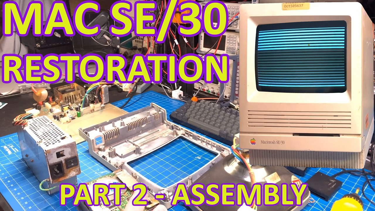
Macintosh SE/30 – Restoration Part 2 – Re-assembly

In the latest installment of the Macintosh SE/30 restoration series, the host dives back into the intricacies of reassembling a classic piece of computing history. After tackling severe corrosion issues in the previous video, the focus shifts to reassembling the cleaned and restored components. The host shares insights into the process, showcasing a beautifully restored frame that has been treated with Rustoleum cold galvanized paint, effectively eliminating rust and corrosion. While some stains remain on the faceplate—likely from leaked alkaline—the restoration is progressing well, setting the stage for a successful reassembly.

Restoring the Core Components

One of the significant challenges faced by the host was dealing with the analog board, which had suffered extensive corrosion. Instead of using the original damaged board, the restoration involves a replacement from a donor Macintosh SE. This replacement has been reflowed and soldered to ensure stable connections. The speaker has been carefully reattached with a bit of glue, and new screws have been utilized to replace the corroded originals, ensuring that the assembly remains robust and reliable.

Innovative Upgrades and Modifications

The host also introduces several upgrades to enhance the Macintosh’s performance and usability. While the original hard drive remains installed for aesthetic and monetary value, a Blue SCSI device is integrated to provide modern storage capabilities. A new 3D-printed mount allows for a more seamless installation, ensuring that the Blue SCSI fits flush with the case. This modification exemplifies the blend of vintage technology with modern solutions, creating a more functional and appealing system.

Enhancing the Motherboard

Moving on to the motherboard, the host showcases various enhancements, including the installation of a coin cell battery insert and upgraded RAM. The use of purple RAM and ROM not only adds a visual flair but also allows for customization and improved performance. The host emphasizes the importance of using 3D-printed clips to secure the newer RAM, which ensures stability and prevents potential issues during operation. These thoughtful upgrades help revitalize the Macintosh SE/30, allowing it to meet contemporary standards while retaining its classic charm.

Final Testing and Observations

As the assembly comes together, the host takes the time to test the system before sealing it up entirely. The excitement is palpable as the Macintosh boots up successfully, revealing a vibrant screen free from burn-in or blurriness. The careful adjustments and meticulous cleaning have paid off, resulting in a machine that looks almost as good as new. While there are still minor cosmetic imperfections, the overall restoration is impressive, promising a rewarding experience for anyone who gets to use this classic computer.

With the project nearing completion, the host expresses enthusiasm for the potential of the restored Macintosh SE/30. The journey of bringing this vintage machine back to life showcases not only the technical skills involved but also the joy of preserving computing history. As the video wraps up, viewers are left eager for the next installment, where the restoration of additional components from the donor SE will be explored in further detail.

Back again with this SE/30. Let's put it all back together.

Watch on YouTube: Macintosh SE/30 – Restoration Part 2 – Re-assembly

Subscribe: Click here